Articles | Marine | Steam Blowing
Steam Blowing Handbook
1. What is Steam Blowing?
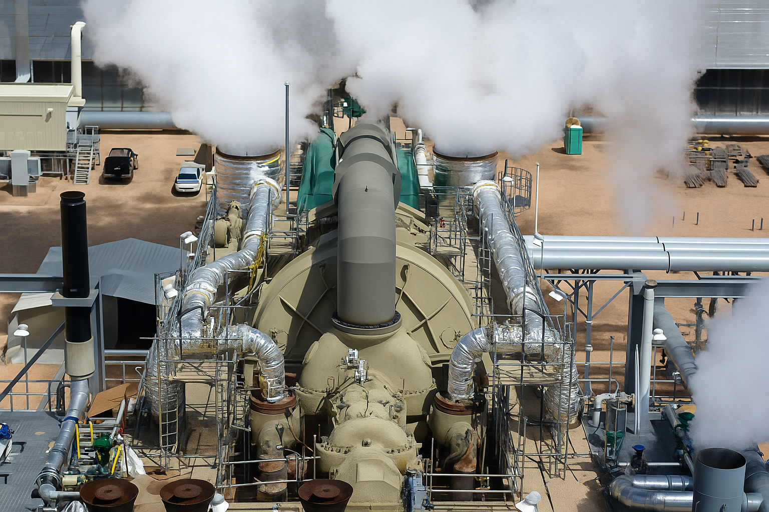
Steam blowing is a pre-operational cleaning process used primarily in thermal power plants and industrial steam systems. It involves the controlled release of high-velocity steam through piping, boilers, and connected equipment to remove loose debris, welding slag, rust, oil, and other contaminants.
The primary purpose is to ensure the internal cleanliness of steam lines and components before exposing sensitive equipment such as steam turbines, control valves, and heat exchangers to live steam. Any residual particles left inside the piping during construction or fabrication may lead to erosion, pitting, mechanical damage, or catastrophic failure once the system is in full operation.
Key Notes
- It simulates extreme conditions of pressure and flow to dislodge and carry out foreign particles
- It is usually conducted after chemical cleaning and hydrotesting.
- Systems cleaned include boilers, superheaters, reheaters, and steam mains.
- It is critical in high-pressure/high-temperature applications, particularly in power plants and refineries.
2. Types of Steam Blowing
Description
Steam is accumulated in a temporary reservoir or piping section and suddenly released through a quick-opening valve, creating a powerful surge and high velocity to dislodge debris.
When to use
New or heavily contaminated lines; ideal for steam turbines, generators, and critical equipment
Pressure/Flow
High pressure (~40–100 bar) released in bursts; high velocity (~Mach 1).
Typical Duration
Several cycles over 1–2 days
Mechanical Impact
Very high (shock effect)
Advantages
High removal effectiveness. Simulates real operation impact.
Disadvantages
Requires large steam volume and planning. Risk of mechanical damage.
Description
Steam is allowed to flow continuously through the piping system with a steady-state condition until cleanliness is achieved.
When to Use
Clean or short piping runs, low debris, chemical pre-cleaned systems.
Pressure/Flow
Moderate pressure (20–50 bar) with constant flow.
Typical Duration
Continuous for 6–24 hours
Mechanical Impact
Low to moderate
Advantages
Safer for fragile piping. Less noise
Disadvantages
May be less effective at removing heavy debris.
Notes
- Puffing is most aggressive/efficient but needs robust supports and restraint design.
- Continuous is gentler and safer but may take longer and consume more steam.
3. Best Steam Blowing Method for Your System Design
For appropriate steam blowing type selection, evaluate the system’s condition, its level of criticality, and the design pressure.
Selection Criteria
- Critical steam lines like those leading to turbines, puffing with target plate will ensure debris were removed efficiently
- Service lines, secondary steam lines continuous of Peak flow is most recommended reducing cost and mechanical damage
- Where sensitive components like thin pipes or heat exchangers are to be cleaned, continuous blowing at low pressure will avoid fatal damage to these parts.
- Lines where large volumes of debris or internal weld slag are deposited, frequent puffing is the most effective
Before deciding which type of steam blowing to apply, carefully assess the system’s condition and determine how critical it is:
| Pressure Range | Recommended Type | Precautions |
|---|---|---|
| < 10 bar | Continuous or Peak Flow | Low cleaning impact. May not effectively remove hard residues. |
| 10 – 40 bar | Puffing or Continuous | Stress evaluation of piping and equipment is required. |
| > 40 bar | Puffing with strict control | Risk of thermal & pressure shock. Use restrictors to control surge forces. |
| > 100 bar | Mixed with staged control | Requires detailed planning, staged pressurization, and use of relief valves. |
4. Acceptance Criteria
The acceptance criteria define when the steam blowing process can be considered successfully completed, ensuring the piping and equipment are sufficiently clean and free of damaging debris before commissioning.
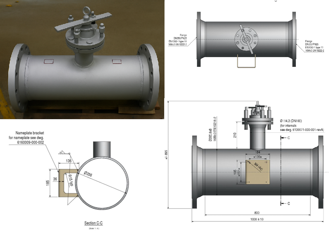
4.1 Target Plates (Most Common Method)
Purpose: Target plates (also called witness plates) are metal plates installed at the outlet or discharge point of the steam blowing line.
Function: They physically catch debris such as welding slag, metal fragments, rust, and scale during the blowing.
Evaluation
- Plates are inspected visually for the presence of particles or marks.
- Acceptance criterion: three consecutive clean plates (no significant particles).
- Plates are photographed and documented as proof for quality control and client acceptance.
Advantages
- Simple, reliable, and inexpensive method.
- Provides direct visual confirmation of debris removal.
Limitations
- Only captures debris large enough to leave visible marks.
- Requires manual handling and inspection.
- Not suitable for microscopic or suspended particles.
4.2 Borescope Inspection (Used in Critical Cases like Steam Turbines)
Purpose: To visually inspect the internal surfaces of piping and critical equipment after blowing.
How It Works
- A flexible fiber-optic or video endoscope is inserted into the piping to look for residual debris, weld spatter, or surface damage.
- Allows detection of small particles or localized deposits not caught by target plates.
Advantages
- Provides direct visual evidence inside the system.
- Can identify problem areas that require additional cleaning or repair.
Limitations
- Requires specialized equipment and skilled operators.
- More time-consuming and costly than target plates.
4.3 Measurement of Suspended Particles
Purpose: To quantify fine particulate matter remaining suspended in the steam or condensate after blowing.
How It Works
- Use of particle counters or optical sensors that analyze the number and size of particles in the steam flow or condensate.
- Samples may be collected and analyzed in laboratories.
Application
- Critical for systems where microscopic debris can cause erosion, corrosion, or damage—like high-speed turbines or precision valves.
- Sometimes used alongside target plates and endoscopy to ensure comprehensive cleanliness.
Advantages
- Objective, quantitative data on system cleanliness.
- Can detect particles too small for visual methods.
Limitations
- Requires sophisticated instruments and procedures.
- Higher operational cost.
5. Target Plates — Function & Types
Main Function
Target plates visually verify the effectiveness of steam blowing. Placed at the line exit, they capture solid particles and metallic debris. Cleaning is satisfactory when three consecutive plates return nearly clean.
5.1. Common Target Plate Materials
| Material | Reason for Choice | Notes |
|---|---|---|
| Aluminium | Soft, easy to mark; low cost | Ideal for small particles; clear impacts |
| Stainless Steel (AISI 304/316) | High resistance; high temperature / abrasive debris | Sometimes reusable; requires analysis |
| Copper | High thermal conductivity; malleable | Rare; special tests |
| Brass | Good visibility of impacts; moderate heat resistance | Alternative to aluminium |
Note: Aluminium is most common (especially in medium-pressure systems) because its deformation makes metal particles easy to spot.
5.2. Types of Target Plate Systems (most used)
🔩
Bolted Target Plate (Manual)
- Simple support with holes; plate fixed with screws or clamps.
- Advantage: low cost, easy maintenance.
- Disadvantage: operation must be stopped for replacement.
⚙️
Hydraulic / Pneumatic Retractable Cassette
- Actuator moves plate in/out of line; allows installation on pressurized ducts.
- Best where access is difficult or hazardous.
- Advantage: safer in high-risk conditions.
- Disadvantage: higher cost.
5.3. Cleanliness Assessment
- Visible residues: metal particles, slag, oxidation scales, or crusted dirt.
- Photographic record of each plate.
- Optionally complement with:
- Borescope inspection
- Optical sensors to measure suspended particles
5.4. Target Plate Dimensions
- Diameter: at least 1.2–1.5× the pipe diameter.
- Thickness: 0.5–3 mm (depends on material).
- Installation: 2–4 m downstream of the blowing point.
| Target Type | Installation Method | Cost | Ideal Application |
|---|---|---|---|
| Fixed Aluminium | Manual with screws | Low | Simple projects |
| Stainless Steel Cassette | Hydraulic or pneumatic | High | High-pressure or risk systems |
6. General Procedures
Before Blowing
- Hydrostatic testing complete.
- Check supports, clearances, anchors.
- Install silencers/deflectors; position target plates.
During
- Steam heated above saturation temperature (superheated)
- Operate in pulses (puffing) or continuous flow.
- Monitor vibration and noise.
After
- Inspect plates;
- prepare cleaning report;
- obtain client/inspector approval.
7. Common Equipment
- Temporary boiler (or plant steam)
- Quick-opening blow-off valve
- Bypass piping for silencers
- Target plates (aluminium or stainless steel)
- Acoustic silencer
- Pressure/temperature gauges
8. Standards & Technical References
- ASME B31.1 / B31.3 (cleaning and pressure)
- ASTM A106 / A105 (materials)
- GEK 110483A (GE Steam Blowing Requirements)
- Siemens Steam Turbine Guidelines
- VGB PowerTech Recommendations
9. Calculations
At Cassia Marine, we typically use two methods of steam blowing:
- Continuous Steam Blow
- Intermittent Steam Blow
Regardless of the technique used, the goal of steam blowing is to forcefully pass a sufficient volume of steam through the relevant system components to dislodge and remove debris and contaminants. These particles, if left behind, could otherwise be carried into the steam turbine during normal operation.
It’s important to note that steam blowing is not an absolute method of decontamination it won’t eliminate every trace of material. For instance, stubborn residues like mill scale may remain adhered to the surfaces. However, complete removal is not necessary. What matters is ensuring that any residue left behind is secure enough not to be dislodged under standard operating conditions.
To achieve this, the cleaning forces applied during steam blowing must exceed those encountered during regular turbine operation. This comparison is quantified using the Cleaning Force Ratio (CFR), also known as the Disturbance Factor (DF).
9.1 Cleaning Force Ratio – CFR
The Cleaning Force Ratio (CFR) compares the dynamic cleaning force generated during steam blowing to the force the system will experience during normal turbine operation.
Cleaning Force Ratio
CFR
=
Cleaning Force Ratio
CFR
=
Where:
- ρ = steam density (kg/m3)
- v = steam velocity (m/s)
- Subscripts “blow” and “normal” refer to steam-blowing and normal operation conditions.
Target CFR Values
- CFR > 1.0: Minimum acceptable (cleaning force exceeds normal operation).
- CFR = 1.2–1.5: Common engineering target with safety margin.
- CFR ≥ 2.0: Used for critical systems / to speed up cleaning.
9.2 Example Calculation
Steam Turbine Requirements (Normal Operation):
- Mass flow rate m = 50 t/h = 13.89 kg/s
- Pressure = 40 bar
- Temperature = 400 °C
- Pipe size DN300 → internal area A ≈ 0.0707 m²
- Steam density at 40barρ ≈ 8.0 kg/m³ (from steam tables)
Step 1: Calculate steam velocity during normal operation
Normal Steam Velocity
vnormal =
=
=
≈ 24.56 m/s
Steam Blowing (Objective: CFR ≥ 1.2):
Let’s assume we use the same pressure and temperature for steam blowing:
- 40 bar / 400 °C → steam density remains ≈ 8.0 kg/m³
- Pipe size unchanged
- Temperature = 400 °C
Step 2: Blowing velocity for CFR ≥ 1.2
Blowing velocity for CFR ≥ 1.2
CFR=
⇒ vblow ≥ √1.2 · vnormal= 1.095 · 24.56 ≈ 26.9 m/s
Step 3: Calculate required mass flow for blowing
Mass Flow for Blowing
ṁblow = ρblow · A · vblow = 8.0 · 0.0707 · 26.9 ≈ 15.2 m/s = 54.7 t/h
Final Result:
To ensure CFR ≥ 1.2 for safe and effective steam blowing of a pipeline designed for 50 t/h at 40 bar and 400 °C, you should perform steam blowing with at least:
Results
- Steam flow: 54.7 t/h
- Steam velocity: 26.9 m/s
- CFR: 1.2 or higher
This confirms that the cleaning force will exceed what the system experiences during real turbine operation, minimizing the risk of residual particles damaging the turbine.
While CFR (Cleaning Force Ratio) is the core calculation for determining the effectiveness of steam blowing, it is not the only parameter Cassia Marine Engineers consider when planning and executing a proper steam blowing operation.
Here’s a breakdown of additional key calculations and considerations used alongside CFR:
9.3 Other Key Calculation and Analyzes in the Process
Target Plate Impact Assessment
After each blow, target plates are installed in the steam path to capture debris. The number, size, and type of impact marks are compared to the turbine manufacturer’s acceptance criteria.
Analyzes
- Install plates at discharge to capture debris
- Count and classify visible impacts per cm² against OEM acceptance limits (e.g., ≤ 5 light impacts/cm²; no heavy impacts).
- Document and photograph each plate
Noise Level (SPL) Check
Steam blowing can be extremely loud, so you may need to calculate or simulate sound pressure level (SPL) at 1 m or 50 m from the blow-off silencer. This depends on:
- Blow-off pressure
- Orifice/silencer design.
- Steam flow velocity
Noise Level Calculation
SPL (dB) ~ 20 · log10 (
)
Where:
- P is sound pressure
- Pref is the reference pressure (tipically 2 x 10⁻⁵Pa)
- Subscripts “blow” and “normal” refer to steam-blowing and normal operation conditions.
Why it’s important: To meet site safety limits (usually < 85 dB at 50 ft)
Thermal Stress Assessment
Steam blowing involves rapid pressurization and depressurization, causing thermal cycles in pipes and supports.
You may need to check that
- Number of blows doesn’t exceed stress cycle limits (e.g., < 10 cycles)
- Allowable temperature changes are not exceeded
- Pre-warming and cooling steps are properly calculated
No simple formula — this is often done via pipe stress analysis software (Cassia Marine will use CAESAR II or AutoPIPE).
Temporary Piping Sizing and Velocity Check
If you use temporary piping, ensure velocity is not too high (to avoid erosion) or too low (to maintain CFR). Rule of thumb:
- Max safe velocity: Mach 0.5–0.6 (≈ 500–600 m/s for steam at typical blowing conditions).
- Temporary piping must withstand pressure and temperature of the blow
We will calculate:
Piping Sizing and Velocity Check
v =
Where
- m is mass flow (kg/s),
- A is cross-sectional area (m²)
- ρ is steam density (kg/m³)
- v<500–600 m/s and within pressure rating
Pressure Drop Calculations (ΔP)
If using temporary silencers or long blow lines, you’ll need to verify the pressure drop across the system is acceptable.
Use the Darcy-Weisbach equation:
Pressure Drop Calculations (ΔP)
ΔPnormal = f ·
·
Where:
- f = friction factor
- L = pipe length
- D = pipe diameter
- v = steam velocity
- ρ = steam density
Number of Blows and Cleaning Curve
You’ll track blow count vs. target plate quality and CFR. The steam blow is only complete when:
- CFR ≥ required minimum (e.g. 1.2 or 2.0)
- Target plate impacts are within limits
- No large fluctuations in debris observed in successive blows
9.4 Additional Engineering Checks (summary)
| Area | Purpose | Inputs / Tools |
|---|---|---|
| CFR | Ensure cleaning force is sufficient | Flow rate, pipe size, density |
| Target Plate Impacts | Confirm debris removal visually | Impact plate, OEM criteria |
| SPL / Noise | Safety for people/environment | Blow pressure, silencer design |
| Thermal Stress | Protect piping from fatigue | Blow count, temp cycles; CAESAR II/AutoPIPE |
| Temporary Piping | Velocity & pressure rating check | v = m / (ρ·A); keep v < 500–600 m/s |
| Pressure Drop (ΔP) | Ensure system pressure adequacy | Darcy–Weisbach; L, D, v, ρ, f |
| Number of Blows | Control quality vs over-cleaning | CFR, plate quality vs blow count |
Related Articles

STEAM BLOWING HANDBOOK

Welcome to Cassia Marine Website
